
GENESIS NG3 - Pneumatic tool AVDEL - Free user manual and instructions
Find the device manual for free GENESIS NG3 AVDEL in PDF.
User questions about GENESIS NG3 AVDEL
0 question about this device. Answer the ones you know or ask your own.
Ask a new question about this device
Download the instructions for your Pneumatic tool in PDF format for free! Find your manual GENESIS NG3 - AVDEL and take your electronic device back in hand. On this page are published all the documents necessary for the use of your device. GENESIS NG3 by AVDEL.
USER MANUAL GENESIS NG3 AVDEL
Safety Instructions 4
Specifications
Tool Specification 5
Tool Dimensions 5
Intent of Use
Range of Fasteners 6
Part Numbering 6
Putting into Service
Air Supply 7
7
Nose Assemblies
Fitting Instructions 8
Servicing Instructions 8
9-12
Type 1 Standard 9
Avseal® II Nose Tips 10
Type 2 Limited Access 11
Type 3 Aerospace 11
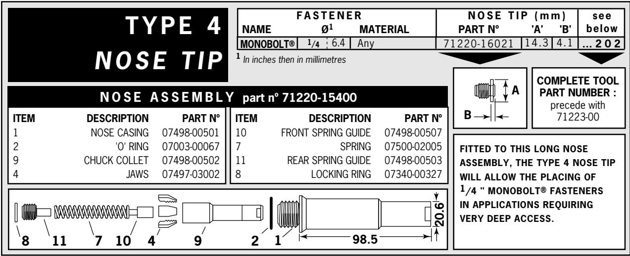
Type 4 Monobolt®-Extended 12
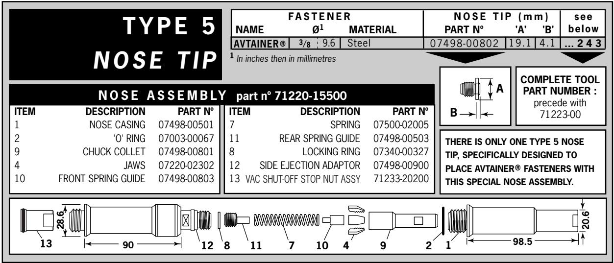
Type 5 Avtainer® 12
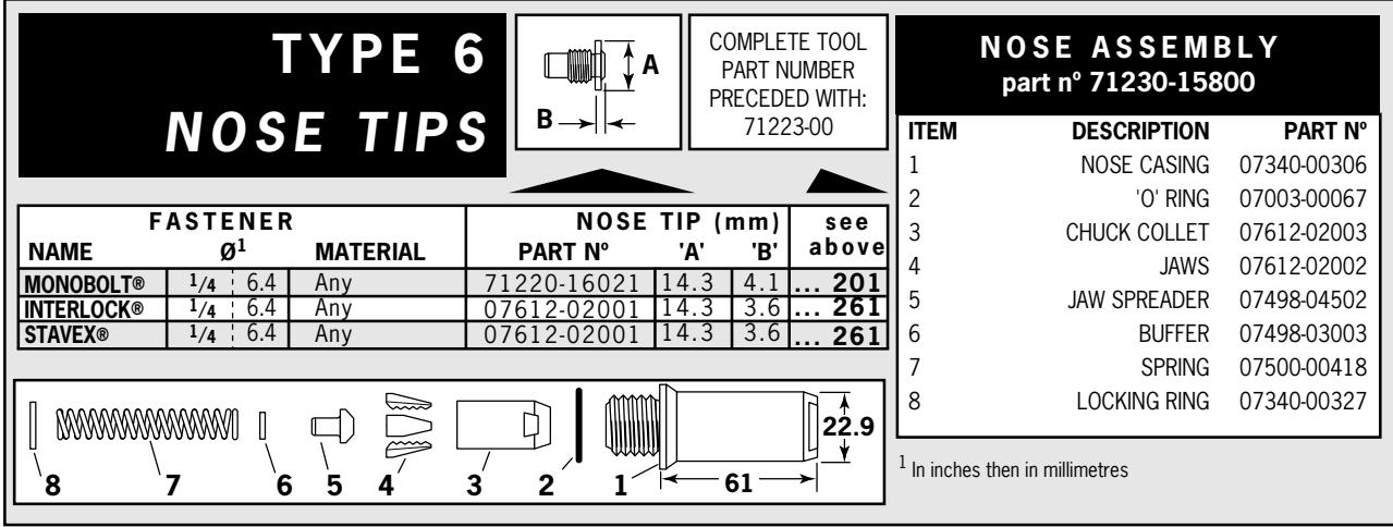
Type 6 Monobolt® - Interlock® 12
Accessories
Stem Deflector 13
Preparing the Base Tool for use with Stem Deflector 13
Extension 13
Swivel Heads 14
Straight Swivel Head capability 14
Preparing the Base Tool for Right-Angle and Straight 15
Swivel Head Attachment
Right-Angle Swivel Head capability 15
Swivel Head Fitting Instructions 16
Swivel Head Servicing Instructions 17
Constant Components 17
Servicing the Tool
Daily/Weekly 18
Moly Lithium Grease EP 3753 Safety Data 18
Molykote 55m Grease Safety Data 19
Molykote® 111 Grease Safety Data 19
Service Kit 20
Maintenance 20
Nose Equipment 20
Dismantling the Tool 21
Head Assembly 21
Pneumatic Piston Assembly 22
Air Valve 22
Rotary Valve 23
Trigger 23
Stop Plate Assembly (71213-03900) 24
General Assembly of Base Tool
General Assembly 26
Parts List 27
Priming
Oil Details 28
Hyspin® VG 32 Oil Safety Data 28
Priming Kit 28
29
Fault Diagnosis
Symptom, Possible Cause and Remedy 30
Francais 33
Deutsch 63
Italiano 93
LIMITED WARRANTY
Avdel make the limited warranty that its products will be free of defects in workmanship and materials which occur under normal operating conditions. This Limited Warranty is contingent upon: (1) the product being installed, maintained and operated in accordance with product literature and instructions and (2) confirmation by Avdel of such defect, upon inspection and testing. Avdel makes the forgoing limited warranty for a period of twelve (12) months following Avdel's delivery of the product to the direct purchaser from Avdel. In the event of any breach of the forgoing warranty, the sole remedy shall be to return the defective Goods for replacement or refund for the purchase price at Avdel's option. THE FORGOING EXPRESS LIMITED WARRANTY AND REMEDY ARE EXCLUSIVE AND ARE IN LIEU OF ALL OTHER WARRANTYES AND REMEDIES. ANY IMPLIED WARRANTY AS TO QUALITY, FITNESS FOR PURPOSE, OR MERCHANTABILITY ARE HEREBY SPECIFICALLY DISCLAIMED AND EXCLOSED BY AVDEL.
Avd i t
This instruction manual must be read with particular attention to the following safety rules, by any person installing, operating, or servicing this tool.
1 Do not use outside the design intent.
2 Do not use equipment with this tool/machine other than that recommended and supplied by Avdel UK Limited.
3 Any modification undertaken by the customer to the tool/machine, nose assemblies, accessories or any equipment supplied by Avdel UK Limited or their representatives, shall be the customer's entire responsibility. Avdel UK Limited will be pleased to advise upon any proposed modification.
4 The tool/machine must be maintained in a safe working condition at all times and examined at regular intervals for damage and function by trained competent personnel. Any dismantling procedure shall be undertaken only by personnel trained in Avdel UK Limited procedures. Do not dismantle this tool/machine without prior reference to the maintenance instructions. Please contact Avdel UK Limited with your training requirements.
5 The tool/machine shall at all times be operated in accordance with relevant Health and Safety legislation. In the U.K. the "Health and Safety at Work etc. Act 1974" applies. Any question regarding the correct operation of the tool/machine and operator safety should be directed to Avdel UK Limited.
6 The precautions to be observed when using this tool/machine must be explained by the customer to all operators.
7 Always disconnect the airline from the tool/machine inlet before attempting to adjust, fit or remove a nose assembly.
8 Do not operate a tool/machine that is directed towards any person(s) or the operator.
9 Always adopt a firm footing or a stable position before operating the tool/machine.
10 Ensure that vent holes do not become blocked or covered.
11 The operating pressure shall not exceed 7 bar.
12 Do not operate the tool if it is not fitted with a complete nose assembly or swivel head unless specifically instructed otherwise.
13 Care shall be taken to ensure that spent stems are not allowed to create a hazard.
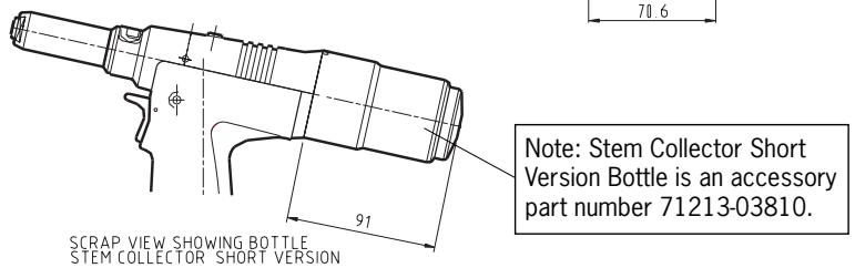
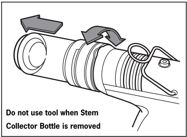
14 Vacuum Air MUST be turned off using the Trigger before removing the Stem Collector Bottle which MUST be emptied when half full.
15 The Tool MUST NOT be operated with the Stem Collector Bottle removed.
16 If the nG3 tool is fitted with a stem deflector, it should be rotated until the aperture is facing away from the operator and other person(s) working in the vicinity.
17 When using the tool, the wearing of safety glasses is required both by the operator and others in the vicinity to protect against fastener ejection, should a fastener be placed 'in air'. We recommend wearing gloves if there are sharp edges or corners on the application.
18 Take care to avoid entanglement of loose clothes, ties, long hair, cleaning rags etc. in the moving parts of the tool which should be kept dry and clean for best possible grip.
19 When carrying the tool from place to place keep hands away from the trigger/lever to avoid inadvertent start up.
20 Excessive contact with hydraulic fluid oil should be avoided. To minimize the possibility of rashes, care should be taken to wash thoroughly.
21 C.O.S.H.H. data for all hydraulic oils and lubricants is available on request from your tool supplier.
Tool Specification
| Air Pressure | Minimum - Maximum | 5-7 bar (72.5 - 101.5 psi) |
| Free Air Volume Required | @ 5.5 bar | 4.3 litres (0.15 cuft) |
| Stroke | Minimum | 26 mm (1.02 in) |
| Pull Force | @ 5.5 bar | 12.9 kN (2900 lbf) |
| Cycle Time | Approximately | 1.2 seconds |
| Noise Level | 75 dB(A) | |
| Weight | Including nose equipment | 2.25 Kg |
| Vibration | Less than | 2.5 m/s² (8.2 ft/s²) |
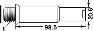
Tool Dimensions
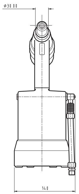
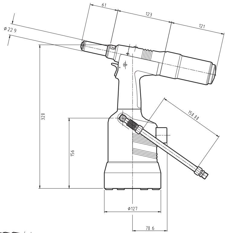
Dimensions in millimetres
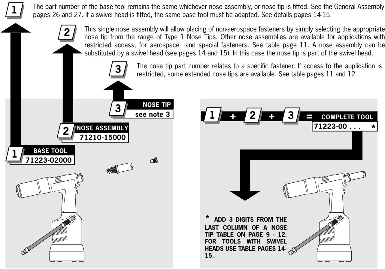
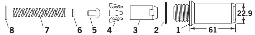
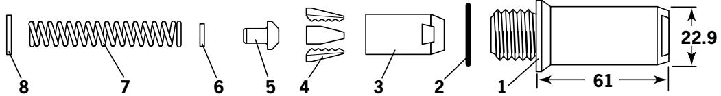
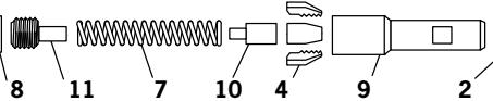
nG3 is a hydro-pneumatic tool designed to place Avdel® breakstem fasteners at high speed making it ideal for batch or flow-line assembly in a wide variety of applications throughout all industries. It can place all fasteners listed opposite.
The tool features a vacuum system for fastener retention and trouble free collection of the spent stems regardless of tool orientation.
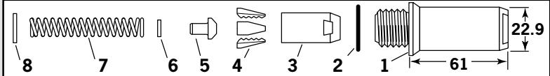
A complete tool is made up of three separate elements which will be supplied individually. See diagram below.
NOSE EQUIPMENT MUST BE Fitted AS DESCRIBED ON PAGE 8.
| TIPO RIVETTO | DIMENSIONI (MM Polici) | ||||||||||||||
| 3 | 3.2 | 4.0 | 4.3 | 4.8 | 5 | 5.2 | 6 | 6.4 | 6.5 | 7 | 8 | 9 | 9.5 | 10 | |
| - | 1/8 | 5/32 | - | 3/16 | - | - | - | 1/4 | - | - | - | - | 3/8 | - | |
| AVEX® | ● | ● | ● | ● | ● | ||||||||||
| STAVEX® | ● | ● | ● | ||||||||||||
| AVINOX® II | ● | ● | ● | ||||||||||||
| AVIBULB® | ● | ● | ● | ● | |||||||||||
| ETR | ● | ||||||||||||||
| BULBEX® | ● | ● | |||||||||||||
| T-LOK® | ● | ● | |||||||||||||
| AVDEL® SR | ● | ● | ● | ● | |||||||||||
| MONOBOLT® | ● | ● | |||||||||||||
| INTERLOCK® | ● | ● | |||||||||||||
| AVTainer® | ● | ● | |||||||||||||
| AVDEL® | ● | ● | ● | ||||||||||||
| MBC® | ● | ● | ● | ||||||||||||
| MBC/LC® | ● | ● | ● | ||||||||||||
| AVSEAL® II | ● | ● | ● | ● | ● | ||||||||||
| Q™ RIVET | ● | ● | ● | ● | |||||||||||
| T™ RIVET | ● | ● | |||||||||||||
| CHERRYMATE™ | ● | ● | |||||||||||||
| KLAMPTITE™ | ● | ● | |||||||||||||
| KLAMPTITE™ KTR | ● | ● | |||||||||||||
Part Numbering
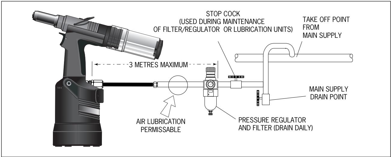
All tools are operated with compressed air at an optimum pressure of 5.5 bar. We recommend the use of pressure regulators and filtering systems on the main air supply. These should be fitted within 3 metres of the tool (see diagram below) to ensure maximum tool life and minimum tool maintenance.
Air supply hoses should have a minimum effective working pressure rating of 150% of the maximum pressure produced in the system or 10 bar, whichever is the highest. Air hoses should be oil resistant, have an abrasion resistant exterior and should be armoured where operating conditions may result in hoses being damaged. All air hoses MUST have a minimum bore diameter of 6.4 millimetres or 1/4 inch.
Operating Procedure
- Ensure that the correct nose assembly suitable for the fastener is fitted.
- Connect the tool to the air supply.
- Insert the fastener stem into the nose of the tool. If using a standard nose assembly, the fastener should remain held in by the vacuum system.
- Bring the tool with the fastener to the application so that the protruding fastener enters squarely into the hole of the application.
- Fully actuate the trigger. The tool cycle will broach the fastener and with standard nose assemblies the broken stem will be projected to the rear of the tool into the collector bottle.
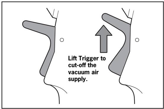
- A partial rotation and pull movement removes the collector bottle. The Trigger should be lifted to cut-off the vacuum supply air prior to removing the collector bottle.
- To minimise air consumption, the trigger should be "lifted" to cut-off the vacuum air supply if the tool is not to be used for a period of time.
Nose Assemblies
Fitting Instructions
IMPORTANT
Nose assemblies do NOT include nose tips. Nose tips must be ordered separately.
A complete tool must always be fitted with the correct nose assembly and nose tip for your fastener and must be ordered separately, refer to the 'NOSE TIPS' tables on pages 9 to 12.
If your application presents no access restriction use a Type '1' Nose Tip unless you are placing aerospace fasteners which requires a Type '3' Nose Tip or Avtainer® fasteners a Type 5 Nose Tip.
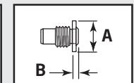
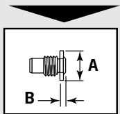
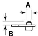
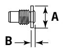
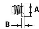
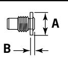
Dimensions 'A' and 'B' in the following Nose Tip tables will help you assess the suitability of a particular nose tip.
You should also check that the dimensions of the nose casing will not restrict access to your application. If access is restricted Type '2' Nose Tips are available for some fasteners. Refer to the table on page 11.
It is essential that nose assembly and nose tip are compatible with the fastener prior to operating the tool.
The Type 4 Nose Tip is an alternative to place 1/4 in Monobolt®. Refer to the table on page 12.
Swivel heads are available as an alternative to nose assemblies as well as an extension when further reach is required.
See pages 14 to 17 in the 'Accessories' section.
IMPORTANT
The air supply must be disconnected when fitting or removing nose assemblies.
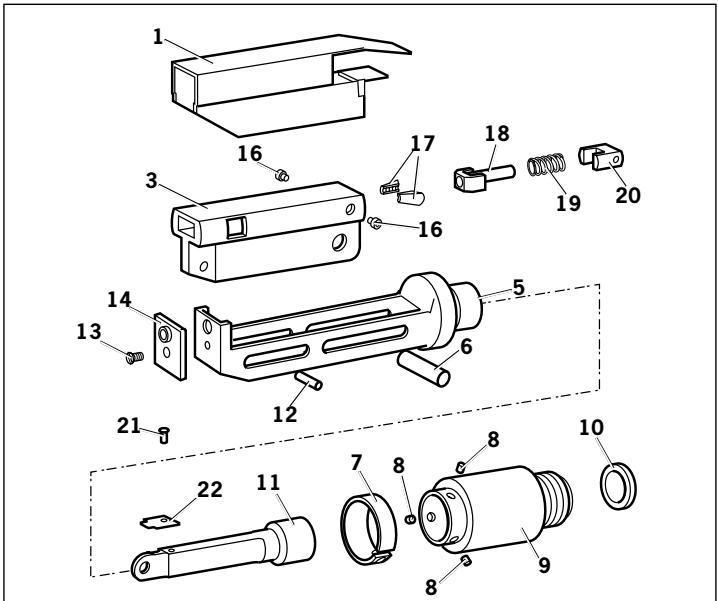
Item numbers in bold refer to nose assembly components in all 5 nose tip tables.
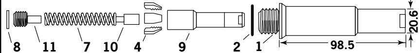
- Lightly coat Jaws 4 with Moly Lithium grease*.
- Drop Jaws 4 into Jaw Housing 3 or Chuck Collet 9 depending on which nose assembly you are using.
- Insert Jaw Spreader 5 into Jaw Housing 3 or insert Front Spring Guide 10 into Chuck Collet 9.
- Locate Buffer 6 on Jaw Spreader 5.
- Locate Spring 7 onto Jaw Spreader 5 or onto Front Spring Guide 10.
Screw Rear Spring Guide 11 into Chuck Collet 9. - Fit Locking Ring 8 onto the Jaw Spreader Housing of the tool.
- Holding tool pointing down, screw the assembled Jaw Housing or Chuck Collet onto the Jaw Spreader Housing and tighten with spanner*.
- Screw the nose tip into Nose Casing 1 and tighten with spanner*.
- Place Nose Casing 1 over Jaw Housing 3 or Chuck Collet 9 and screw onto the tool, tightening with spanner*.
Servicing Instructions
Nose assemblies should be serviced at weekly intervals. You should hold some stock of all internal components of the nose assembly and nose tips as they will need regular replacement.
Use Spanner 07900-00849 (supplied with the tool) to assist when servicing the nose assembly.
- Remove the nose equipment using the reverse procedure to the 'Fitting instructions'.
Any worn or damaged part should be replaced.
Clean and check wear on Jaws. - Ensure that neither the Jaw Spreader nor the Front Spring Guide is distorted.
- Check Spring 7 is not distorted.
-
Assemble according to fitting instructions above.
-
Item included in the nG3 Service Kit. For complete list see page 20.
Nose Tips
TYPE 1 OSE TIPS
1 In inches then in millimetres.
2 Head forming nose tips for use with countersunk heads ONLY.
- In ADDITION to the nose assembly shown below, an extra long nose assembly is available to place 1/4 "Monobolt® in applications with restricted access. See type 4 NOSE TIP table.
NOSE ASSEMBLY part n° 71210-15000
| ITEM | DESCRIPTION | PART N° |
| 1 | NOSE CASING | 07340-00306 |
| 2 | ‘O’ RING | 07003-00067 |
| 3 | JAW HOUSING | 07340-00304 |
| 4 | JAWS | 71210-15001 |
| 5 | JAW SPREADER | 07498-04502 |
| 6 | BUFFER | 71210-05001 |
| 7 | SPRING | 07500-00418 |
| 8 | LOCKING RING | 07340-00327 |
| NAME | FASTENER\( \varnothing^1 \) | MATERIAL | NOSE TIP (mm) | see below | ||
| PART N° | 'A' | 'B' | ||||
| AVEX®Large flange | 1/8 | 3.2 AI Alloy | 71210-05002 | 12.7 | 4.8 | ... 001 |
| 1/8 | 3.2 Steel | 71210-16070 | 12.7 | 3.3 | ... 004 | |
| 1/8 | 3.2 AI Alloy | \( 07340-06401^2 \) | 12.7 | 2.9 | ... 003 | |
| - | 3.0 AI Alloy | 71210-05002 | 12.7 | 4.8 | ... 001 | |
| 5/32 | 4.0 AI Alloy | 71210-16070 | 12.7 | 3.3 | ... 004 | |
| 5/32 | 4.0 Steel | 07381-04701 | 12.7 | 2.8 | ... 010 | |
| 5/32 | 4.0 AI Alloy | \( 07340-06501^2 \) | 12.7 | 3.3 | ... 009 | |
| 3/16 | 4.8 AI Alloy | 07381-04701 | 12.7 | 2.8 | ... 010 | |
| 3/16 | 4.8 AI Alloy | 07340-04800 | 19.0 | 3.3 | ... 016 | |
| 3/16 | 4.8 Steel | 07490-04401 | 12.7 | 3.3 | ... 017 | |
| 3/16 | 4.8 AI Alloy | \( 07340-06601^2 \) | 12.7 | 4.1 | ... 015 | |
| 1/4 | 6.4 AI Alloy | 07612-02001 | 12.7 | 3.3 | ... 021 | |
| MONOBOLT® | 3/16 | 4.8 Any | 71210-16020 | 12.7 | 4.1 | ... 200 |
| BULBEX® | 5/32 | 4.0 AI Alloy | 71210-16070 | 12.7 | 3.3 | ... 004 |
| 3/16 | 4.8 AI Alloy | 07381-04701 | 12.7 | 2.8 | ... 010 | |
| AVINOX®II | 1/8 | 3.2 Stainless Steel | 71210-16070 | 12.7 | 3.3 | ... 004 |
| 5/32 | 4.0 Stainless Steel | 07381-04701 | 12.7 | 2.8 | ... 010 | |
| 3/16 | 4.8 Stainless Steel | 07498-01401 | 12.7 | 4.8 | ... 082 | |
| T-LOK® | - | 4.3 Steel | 07340-06201 | 12.7 | 3.3 | ... 120 |
| 3/16 | 4.8 Steel | 07340-06201 | 12.7 | 3.3 | ... 120 | |
| AVIBULB® | 1/8 | 3.2 Steel | 71210-16070 | 12.7 | 3.3 | ... 004 |
| 5/32 | 4.0 Steel | 07381-04701 | 12.7 | 2.8 | ... 010 | |
| 3/16 | 4.8 Steel | 07498-01401 | 12.7 | 4.8 | ... 082 | |
| - | 6 Steel | 07612-02001 | 12.7 | 3.3 | ... 021 | |
| AVDEL® SR Countersunk | 1/8 | 3.2 Any | 71210-05002 | 12.7 | 4.8 | ... 001 |
| 5/32 | 4.0 Any | 71210-16070 | 12.7 | 3.3 | ... 004 | |
| 3/16 | 4.8 Any | 07348-07001 | 12.7 | 5.7 | ... 062 | |
| 3/16 | 4.8 Any | 71210-16050 | 12.7 | 5.7 | ... 064 | |
| 1/4 | 6.4 Any | 71220-60001 | 12.7 | 3.3 | ... 063 | |
| INTERLOCK® | 3/16 | 4.8 Any | 07381-04701 | 12.7 | 2.8 | ... 010 |
| STAVEX®Large flange Countersunk | 1/8 | 3.2 Steel | 71210-16070 | 12.7 | 3.3 | ... 004 |
| 5/32 | 4.0 Steel | 07381-04701 | 12.7 | 2.8 | ... 010 | |
| 3/16 | 4.8 Steel | 07381-04701 | 12.7 | 2.8 | ... 010 | |
| 3/16 | 4.8 Steel | 07340-04800 | 19.0 | 3.3 | ... 016 | |
| 3/16 | 4.8 Steel | 07381-04701 | 12.7 | 2.8 | ... 010 | |
| 1/8 | 3.2 Stainless Steel | 71210-16070 | 12.7 | 3.3 | ... 004 | |
| 5/32 | 4.0 Stainless Steel | 07381-04701 | 12.7 | 2.8 | ... 010 | |
| 3/16 | 4.8 Stainless Steel | 07381-04701 | 12.7 | 2.8 | ... 010 | |
| QTM RIVET | 1/8 | 3.2 Any | 71210-05002 | 12.7 | 4.8 | ... 001 |
| 5/32 | 4.0 Any | 07340-06201 | 12.7 | 3.3 | ... 120 | |
| 3/16 | 4.8 Any | 07340-06201 | 12.7 | 3.3 | ... 120 | |
| 1/4 | 6.4 Any | 07612-02001 | 12.7 | 3.3 | ... 021 | |
| CHERRYMATE™Large flange | 3/16 | 4.8 Any | 07340-06201 | 12.7 | 3.3 | ... 120 |
| 1/4 | 6.4 Any | 07612-02001 | 12.7 | 3.3 | ... 021 | |
| KLAMPTITE™ KTRLarge flange | 3/16 | 4.8 Any | 71220-16060 | 12.7 | 4.8 | ... 500 |
| 1/4 | 6.4 Any | 71220-16061 | 12.7 | 4.8 | ... 501 | |
| KLAMPTITE™Large flange | 3/16 | 4.8 Any | 07381-04701 | 12.7 | 2.8 | ... 010 |
| 1/4 | 6.4 Any | 07612-02001 | 12.7 | 3.3 | ... 021 | |
| TTM RIVETLarge flange | 3/16 | 4.8 AI Alloy | 703-A-25-6TA | 12.7 | 6.35 | ... 380 |
| 3/16 | 4.8 AI Alloy | 703-B-21 | 12.7 | 6.35 | ... 381 | |
| 3/16 | 4.8 AI Alloy/Steel | 703-A-25-6T | 12.7 | 6.35 | ... 383 | |
| Large flangeLarge flange | 3/16 | 4.8 AI Alloy/Steel | 703-B-26 | 12.7 | 6.35 | ... 384 |
| 1/4 | 6.4 AI Alloy | 743-A-25-8TA | 12.7 | 6.65 | ... 385 | |
| 1/4 | 6.4 AI Alloy | 703-B-21 | 12.7 | 6.65 | ... 386 | |
| 1/4 | 6.4 AI Alloy/Steel | 743-A-25-8T | 12.7 | 6.65 | ... 387 | |
| 1/4 | 6.4 AI Alloy/Steel | 743-B-26 | 12.7 | 6.65 | ... 388 | |
COMPLETE TOOL
PART NUMBER :
precede with
71223-00
AVSEAL®II NOSE TIPS
| FASTENER NAME Ø MATERIAL | NOSE ASSEMBLY | NOSE TIP (mm) PART N° | A' | B' | see below | |||
| AVSEAL®II | - | 6.0 | Standard Al. Alloy - Flush Nose Tip | 71210-16100 | 71210-16104 | 12.7 | 2.5 | ...407 |
| - | 6.0 | Standard Al. Alloy - 2mm Extended Nose Tip | 71210-16100 | 71210-16108 | 12.7 | 5.4 | ...408 | |
| - | 6.0 | Standard Al. Alloy - 8mm Extended Nose Tip | 71210-16100 | 71210-16112 | 12.7 | 11.4 | ...409 | |
| - | 6.5 | Standard Al. Alloy - Flush Nose Tip | 71210-16100 | 71210-16114 | 12.7 | 2.5 | ...413 | |
| - | 6.5 | Standard Al. Alloy - 2mm Extended Nose Tip | 71210-16100 | 71210-16115 | 12.7 | 5.4 | ...414 | |
| - | 6.5 | Standard Al. Alloy - 8mm Extended Nose Tip | 71210-16100 | 71210-16116 | 12.7 | 11.4 | ...415 | |
| - | 7.0 | Standard Al. Alloy - Flush Nose Tip | 71210-16100 | 71210-16105 | 12.7 | 2.5 | ...410 | |
| - | 7.0 | Standard Al. Alloy - 2mm Extended Nose Tip | 71210-16100 | 71210-16109 | 12.7 | 5.4 | ...411 | |
| - | 7.0 | Standard Al. Alloy - 8mm Extended Nose Tip | 71210-16100 | 71210-16113 | 12.7 | 11.4 | ...412 | |
| - | 8.0 | Standard & Low Pressure - Flush Nose Tip | 71220-16100 | 71220-16102 | 14.3 | 2.5 | ...413 | |
| - | 8.0 | Standard & Low Pressure - 2mm Ext Nose Tip | 71220-16100 | 71220-16103 | 14.3 | 5.4 | ...414 | |
| - | 8.0 | Standard & Low Pressure - 8mm Ext Nose Tip | 71220-16100 | 71220-16104 | 14.3 | 11.4 | ...415 | |
| - | 9.0 | Low Pressure Al. Alloy - Flush Nose Tip | 71220-16100 | 71220-16105 | 12AF | 3.3 | ...430 | |
| - | 9.0 | Low Pressure Al. Alloy - 2mm Ext Nose Tip | 71220-16100 | 71220-16106 | 12AF | 5.4 | ...431 | |
| - | 9.0 | Low pressure Al. Alloy - 8mm Ext Nose Tip | 71220-16100 | 71220-16107 | 12AF | 11.4 | ...432 | |
NOSE ASSEMBLY part n² 71210-16100
| ITEM | DESCRIPTION | PART N° |
| 1 | NOSE CASING | 07340-00306 |
| 2 | ‘O’ RING | 07003-00067 |
| 3 | JAW HOUSING | 07340-00304 |
| 4 | JAWS | 71210-16101 |
| 5 | JAW SPREADER | 07498-04502 |
| 6 | BUFFER | 71210-05001 |
| 7 | SPRING | 07500-00418 |
| 8 | LOCKING RING | 07340-00327 |

COMPLETE TOOL PART NUMBER: precede with 71223-00.

Note: Items 9 and 10 are not required when assembling Type 2 or Type 3 Nose Tip to the Base Tool nG3 (71223-02000).

Note: Items 9 and 10 are not required when assembling Type 2 or Type 3 Nose Tip to the Base Tool nG3 (71223-02000).
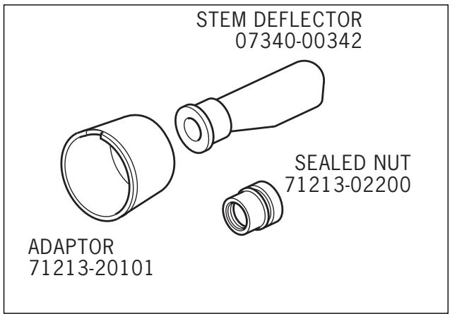
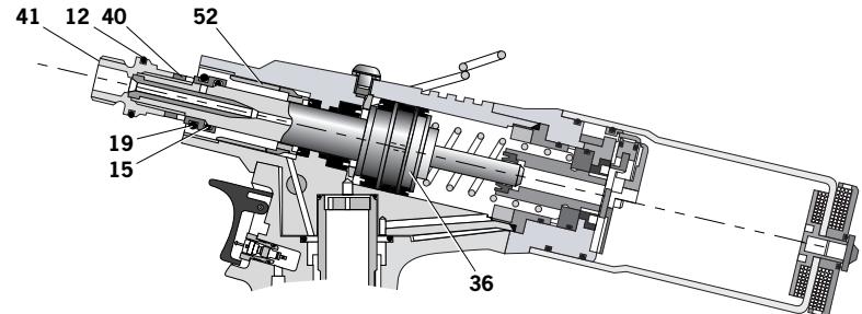
Stem Deflector
The stem deflector is a very simple alternative to the standard stem collector and allows access in restricted areas. To replace the stem collector with the stem deflector proceed as follows:
Preparing the Base Tool for use with Stem Deflector
The airline must be disconnected before any servicing or dismantling.
'Sealed' Nut 71213-02200 replaces Locknut 40 (to cut-off air supply to Vacuum System) as follows:
- Loosen Locknut 40 using 16mm AF Spanner.
- Unscrew and remove both Jaw Spreader Housing 41 and Locknut 40.
- Replace Locknut 40 with 'Sealed' Nut 71213-02200, screw 'Sealed' Nut onto Piston 36 to disable Vacuum System.
- Jaw Spreader Housing 41 must be tightened onto Piston 36, finally tightening 'Sealed' Nut against it.
- Remove Stop Plate Assembly (page 24) by unscrewing Screws 89 (2off).
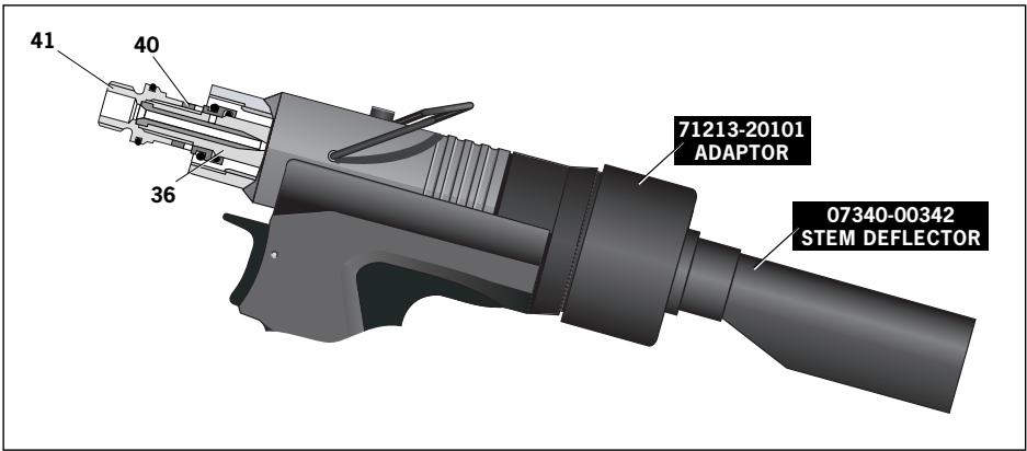
- Fit Stem Deflector (07340-00342) into Adaptor (71213-20101).
- Push the assembled Stem Deflector and Adaptor over Bottle Adaptor 32 and align with the cut-out feature.
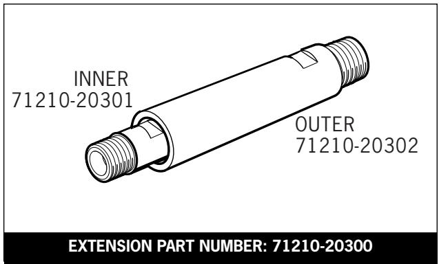
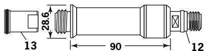
Extension
Fitted between the tool and the nose assembly the extension allows access into deep channels.
- To fit the extension, remove any nose assembly components.
Screw the inner extension to Jaw Spreader Housing 41.
Screw the outer onto Head Assembly 58. - Fit the nose assembly onto the extension.
Item numbers in bold refer to the general assembly drawing and parts list on pages 26 and 27.
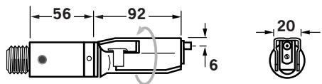
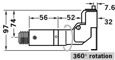
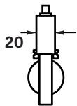
Instead of a nose assembly, a swivel head can be fitted to a base tool. It allows 360^ rotation of the tool about the nose tip and allows access into many applications otherwise too restrictive. There are two types of swivel heads: the straight swivel head with the nose tip slightly offset from the centre line of the tool head and the right-angle swivel head with the nose tip on a perpendicular axis to the head of the tool. See drawings below for dimensions and pages 16 and 17 for detail.
IMPORTANT
PRIOR to fitting a swivel head, the base tool must be adapted. See Preparing the base tool opposite. In contrast to nose assemblies part numbers of swivel heads do INCLUDE a nose tip as shown below.
Swivel heads are supplied separately for fitting to a base tool forming a complete tool. See table below for part numbers. Jaws and nose tips vary depending on the fastener to be placed but all other components remain the same within each type of swivel head. See the 'capability' tables below and page 15. For the 'Constant Components' table see page 17.
'A' and 'B' dimensions will help you assess the accessibility of your application.
STRAIGHT SWIVEL HEAD capability
| FASTENER NAME | ∅1 | MATERIAL | SWIVEL HEAD PART N° | NOSE TIP (mm) PART N° | 'A' | 'B' | JAWS PART N° | see below |
| AVEX® | 1/8:3.2 | Al Alloy | 07345-03000 | 07345-03600 | 7.87 | 3.81 | 07340-00213 | ...001 |
| 1/8:3.2 | Steel | 07345-03100 | 07345-03700 | 7.87 | 3.81 | 07340-00213 | ...004 | |
| 5/32:4.0 | Al Alloy | 07345-03100 | 07345-03700 | 7.87 | 3.81 | 07340-00213 | ...004 | |
| 5/32:4.0 | Steel | 07345-03200 | 07345-03800 | 7.87 | 3.81 | 07490-04602 | ...010 | |
| 3/16:4.8 | Al Alloy | 07345-03200 | 07345-03800 | 7.87 | 3.81 | 07490-04602 | ...010 | |
| BULBEX® | 5/32:4.0 | Al Alloy | 07345-03100 | 07345-03700 | 7.87 | 3.81 | 07340-00213 | ...004 |
| 3/16:4.8 | Al Alloy | 07345-03200 | 07345-03800 | 7.87 | 3.81 | 07490-04602 | ...010 | |
| AVINOX® II | 1/8:3.2 | Stainless Steel | 07345-03100 | 07345-03700 | 7.87 | 3.81 | 07340-00213 | ...004 |
| 5/32:4.0 | Stainless Steel | 07345-03200 | 07345-03800 | 7.87 | 3.81 | 07490-04602 | ...010 | |
| AVSEAL® II | -:4 | Al Alloy | 71213-06000 | 71213-16401 | 6.35 | 1.95 | 07340-00213 | ...160 |
| -:4 | Al Alloy | 71213-06600 | 71213-164022 | 6.35 | 4.11 | 07340-00213 | ...180 | |
| -:5 | Al Alloy | 71213-06100 | 71213-16403 | 7.62 | 2.00 | 07340-00213 | ...161 | |
| -:5 | Al Alloy | 71213-06700 | 71213-164042 | 7.62 | 4.11 | 07340-00213 | ...181 | |
| AVDEL® | 1/8:3.2 | Al Alloy | 07345-03300 | 07345-03301 | 5.08 | 1.17 | 07340-00229 | ...283 |
| 1/8:3.2 | Al Alloy O | 07494-03600 | 07494-03601 | 5.08 | 1.17 | 07340-00229 | ...284 | |
| 1/8:3.2 | Stainless Steel | 07494-03000 | 07494-03011 | 5.08 | 3.81 | 07340-00213 | ...285 | |
| 5/32:4.0 | Al Alloy | 07345-03400 | 07345-03401 | 6.6 | 0.84 | 07340-00229 | ...288 | |
| 5/32:4.0 | Al Alloy O | 07494-03700 | 07494-03701 | 6.6 | 0.84 | 07340-00229 | ...289 | |
| 3/16:4.8 | Al Alloy | 07345-03500 | 07345-03501 | 8.13 | 0.25 | 07498-04401 | ...293 | |
| 3/16:4.8 | Al Alloy O | 07494-03800 | 07494-03801 | 8.13 | 0.25 | 07498-04401 | ...294 | |
| MBC® | 1/8:3.2 | Al Alloy | 07345-04000 | 07165-00701 | 4.75 | 1.9 | 07340-00229 | ...300 |
| 5/32:4.0 | Al Alloy | 07345-04100 | 07165-00702 | 6.35 | 2.36 | 07340-00229 | ...305 | |
| 3/16:4.8 | Al Alloy | 07345-04200 | 07165-00703 | 7.92 | 2.46 | 07498-04401 | ...310 | |
| MBC® L/C | 1/8:3.2 | Al Alloy | 07345-04700 | 07345-04701 | 7.87 | 2.03 | 07340-00229 | ...320 |
| 5/32:4.0 | Al Alloy | 07345-04700 | 07345-04701 | 7.87 | 2.03 | 07340-00229 | ...320 | |
| 5/32:4.0 | Al Alloy O | 07345-04800 | 07345-04701 | 7.87 | 2.03 | 07498-04401 | ...327 | |
| 3/16:4.8 | Al Alloy | 07345-04800 | 07345-04701 | 7.87 | 2.03 | 07498-04401 | ...327 | |
| STAVEX® | 1/8:3.2 | Steel | 07345-03100 | 07345-03700 | 7.87 | 3.81 | 07340-00213 | ...004 |
| 5/32:4.0 | Steel | 07345-03200 | 07345-03800 | 7.87 | 3.81 | |||
| 1/8:3.2 | Stainless Steel | 07345-03100 | 07345-03700 | 7.87 | 3.81 | 07340-00213 | ...004 | |
| 5/32:4.0 | Stainless Steel | 07345-03200 | 07345-0 3800 | 7.87 | 3.81 | 07490-04602 | ...010 |
360^ rotation
1 In inches then in millimetres.
2 Long nose tip for deep placing.
0 Oversize
COMPLETE TOOL PART NUMBER :
precedewith71223-30
(the stop nut and safety cap are included)
IMPORTANT: in contrast to complete tools with nose assemblies, those fitted with swivel heads include the nose tip as a part of the head.
Preparing the Base Tool for Right-Angle and Straight Swivel Head Attachment
- Disconnect the air supply.
- Remove any nose assembly items.
- Remove Stem Collector Bottle Assembly 25 (71213-03800).
- Replace assembly 25 with Safety Cap (71213-20201)
- Unscrew Jaw Spreader Housing 41 and remove with 'O' Ring 12, Locknut 40^ , 'O' Rings 19^ and 15^ , and Seal Housing 52^ . Do not refit these items (*).
- Screw Stop Nut (71213-20200) onto the front of Head Piston 36 as far as it will go by hand.
- Fit Jaw Spreader Housing 41 and 'O' Ring 12, tighten onto Head Piston 36, finally tighten Stop Nut against Jaw Spreader Housing 41.
The tool is now ready to be fitted with a swivel head, see page below.
Item numbers in bold refer to the general assembly drawing and parts list on pages 26 and 27.
Base tool to receive a nose assembly

Base tool to receive a swivel head
RIGHT-ANGLE SWIVEL HEAD capability
| FASTENER NAME | Ø1 | MATERIAL | SWIVEL HEAD PART N° | NOSE TIP (mm) PART N° | 'A' | 'B' | JAWS PART N° | see below |
| AVEX® | 1/8:3.2 | Aluminium Alloy | 07346-03000 | 07345-03600 | 7.87 | 3.81 | 07340-00213 | ...001 |
| 1/8:3.2 | Steel | 07346-03100 | 07345-03700 | 7.87 | 3.81 | 07340-00213 | ...004 | |
| 5/32:4.0 | Aluminium Alloy | 07346-03100 | 07345-03700 | 7.87 | 3.81 | 07340-00213 | ...004 | |
| 5/32:4.0 | Steel | 07346-03200 | 07345-03800 | 7.87 | 3.81 | 07490-04602 | ...010 | |
| 3/16:4.8 | Aluminium Alloy | 07346-03200 | 07345-03800 | 7.87 | 3.81 | 07490-04602 | ...010 | |
| BULBEX® | 5/32:4.0 | Aluminium Alloy | 07346-03100 | 07345-03700 | 7.87 | 3.81 | 07340-00213 | ...004 |
| 3/16:4.8 | Aluminium Alloy | 07346-03200 | 07345-03800 | 7.87 | 3.81 | 07490-04602 | ...010 | |
| AVINOX® II | 1/8:3.2 | Stainless Steel | 07346-03100 | 07345-03700 | 7.87 | 3.81 | 07340-00213 | ...004 |
| 5/32:4.0 | Stainless Steel | 07346-03200 | 07345-03800 | 7.87 | 3.81 | 07490-04602 | ...010 | |
| AVSEAL® II | -:4 | Aluminium Alloy | 71213-04000 | 71213-16401 | 6.35 | 1.95 | 07340-00213 | ...160 |
| -:4 | Aluminium Alloy | 71213-04700 | 71213-164022 | 6.35 | 4.11 | 07340-00213 | ...180 | |
| -:5 | Aluminium Alloy | 71213-04100 | 71213-16403 | 7.62 | 2.00 | 07340-00213 | ...161 | |
| -:5 | Aluminium Alloy | 71213-04800 | 71213-164042 | 7.62 | 4.11 | 07340-00213 | ...181 | |
| STAVEX® | 1/8:3.2 | Steel | 07346-03100 | 07345-03700 | 7.87 | 3.81 | 07340-00213 | ...004 |
| 5/32:4.0 | Steel | 07346-03200 | 07345-03800 | 7.87 | 3.81 | ...010 | ||
| 1/8:3.2 | Stainless Steel | 07346-03100 | 07345-03700 | 7.87 | 3.81 | 07340-00213 | ...004 | |
| 5/32:4.0 | Stainless Steel | 07346-03200 | 07345-0.3800 | 7.87 | 3.81 | 07490-04602 | ...010 | |
| AVDEL® | 1/8:3.2 | Aluminium Alloy | 07346-03300 | 07345-03301 | 5.08 | 1.17 | 07340-00229 | ...283 |
| 1/8:3.2 | Aluminium Alloy O | 07495-03600 | 07494-03601 | 5.08 | 1.17 | 07340-00229 | ...284 | |
| 1/8:3.2 | Stainless Steel | 07495-03000 | 07494-03011 | 5.08 | 3.81 | 07340-00213 | ...285 | |
| 5/32:4.0 | Aluminium Alloy | 07346-03400 | 07345-03401 | 6.6 | 0.84 | 07340-00229 | ...288 | |
| 5/32:4.0 | Aluminium Alloy O | 07495-03700 | 07494-03701 | 6.6 | 0.84 | 07340-00229 | ...289 | |
| 3/16:4.8 | Aluminium Alloy | 07346-03500 | 07345-03501 | 8.13 | 0.25 | 07498-04401 | ...293 | |
| 3/16:4.8 | Aluminium Alloy O | 07495-03800 | 07494-03801 | 8.13 | 0.25 | 07498-04401 | ...294 | |
| MBC® | 1/8:3.2 | Aluminium Alloy | 07346-04000 | 07165-00701 | 4.75 | 1.9 | 07340-00229 | ...300 |
| 5/32:4.0 | Aluminium Alloy | 07346-04100 | 07165-00702 | 6.35 | 2.36 | 07340-00229 | ...305 | |
| 3/16:4.8 | Aluminium Alloy | 07346-04200 | 07165-00703 | 7.92 | 2.46 | 07498-04401 | ...310 | |
| MBC®L/C | 1/8:3.2 | Aluminium Alloy | 07346-04500 | 07345-04701 | 7.87 | 2.03 | 07340-00229 | ...320 |
| 5/32:4.0 | Aluminium Alloy | 07346-04500 | 07345-04701 | 7.87 | 2.03 | 07340-00229 | ...320 | |
| 5/32:4.0 | Aluminium Alloy O | 07346-04600 | 07345-04701 | 7.87 | 2.03 | 07498-04401 | ...327 | |
| 3/16:4.8 | Aluminium Alloy | 07346-04600 | 07345-04701 | 7.87 | 2.03 | 07498-04401 | ...327 |
1 In inches then in millimetres.
2 Long nose tip for deep placing.
0 Oversize
COMPLETE TOOL PART NUMBER :
precedewith71223-40
(the stop nut and safety cap are included)
IMPORTANT: in contrast to complete tools
with nose assemblies, those fitted with swivel
heads include the nose tip as a part of the head.
The fitting and servicing procedures for both types of head are almost identical. Differences are clearly indicated.
IMPORTANT
PRIOR to fitting a swivel head, the base tool must be adapted. See Preparing the base tool opposite. The air supply must be disconnected when fitting or removing swivel heads.
Swivel Head Fitting Instructions
The following procedure will allow you to assemble and fit either of the swivel heads to the tool. If you order a complete swivel head rather than individual components, you will only need to start at stage 'L'.
All moving parts should be lubricated. Unless stated otherwise use Moly Lithium grease (details page 18).
When on grey tint, instructions refer only to the right-angle swivel head. Item numbers in bold refer to illustrations below.
STRAIGHT SWIVEL HEAD
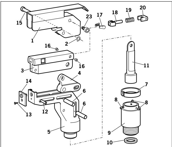
RIGHT-ANGLE HEAD
A Fit Locking Ring 10 over Jaw Spreader Housing 41 (71210-02101). See pages 26 and 27.
B Coat Screw 13 with thread locking adhesive and use to secure Nose Tip 14 onto Body 5.
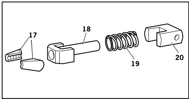
C Lightly lubricate items 17, 18, 19, 20 and insert into Jaw Carrier 3 as shown. Secure with Screws 16.
D Position Lever 4 into Body 5 and hold in place with pin 15 through the hole of Body 5 (not a slot).
E Lubricate the sides of the Jaw Carrier Assembly and insert into Body 5.
F Lubricate Rollers 8 and ENSURE that they will freely rotate in the holes of Adaptor 9. If necessary ream the holes.
G Position Spring Clip 7 over Adaptor 9 past the holes for the rollers and rotate until the locating peg is aligned with the corresponding hole in Adaptor 9 (smallest hole).
H Fit Adaptor 9 over the end of Body 5 and drop Rollers 8 into place. Push Spring Clip 7 over Rollers 8.
Insert Spindle 11 through Adaptor 9 into Jaw Carrier 3 until the hole lines up with slot in Body 5. Temporarily hold in place with Pin 6.
J Insert Pin 12 through the front slot of Body 5 into Jaw Carrier 3.
K Hold the assembly vertical to prevent all pins dropping out and slide the jaw carrier assembly back and forth a few times to ensure free movement. Go to M.
L Remove Screws 23 (4 off) and guard 1. On a straight swivel head also remove Screw 21 and Platform 22.
M Push Pin(s) 6 out and let Spindle 11 drop out. Screw Spindle 11 onto the Jaw Spreader Housing of the tool, leaving the small screw fixing hole uppermost for straight swivel. Tighten gently with a tommy bar.
N Screw the assembly over Spindle 11 onto the tool handle. Replace Pin(s) 6.
0 On straight swivel heads attach Platform 22 onto the top of the Spindle with Screw 21. Deburr the back end of Platform 22 so that it cannot catch on Guard 1.
P Snap Guard 1 over the assembly, align screw holes in guard with tapped holes in body assembly.
Q Insert Pivot Pin 15 through slots in guard and hole in body. Fit Circlip 2 onto pivot pin so that the circlip seats in groove provided.
R Coat the thread of Screws 23 (4 off) with thread locking adhesive and screw into body assembly securing guard to body assembly.
Swivel Head Servicing Instructions
Swivel heads should be serviced at weekly intervals.
- Remove the complete head using the reverse procedure to the 'Fitting instructions' omitting step 'L'.
- If Guard 1 is at all damaged it must be replaced by a new one.
Any worn or damaged parts should be replaced. - Pay particular attention to jaw carrier items in the upper illustration opposite as follows: Check wear on Jaws 17.
Check that Jaw Spreader Tube 18 is not distorted. Check that Spring 19 is neither broken or distorted. Check that Spring Guide 20 is not damaged.
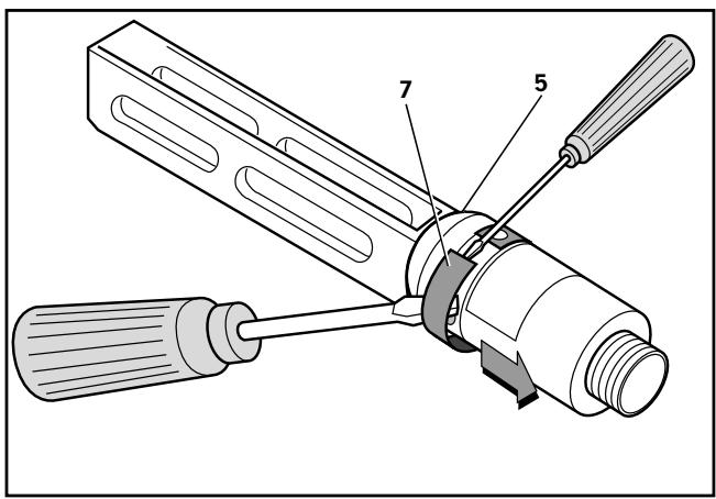
- Check that spring clip 7 is not distorted. When removing Spring Clip 7, use two screwdrivers as shown in the lower illustration opposite.
- Check for excessive wear on slots of Body 5.
- Assemble according to fitting instructions.
Item numbers in bold refer to Swivel Head illustrations on this page. Guard 1 refers to illustration on page 16.
While nose tips and jaws will vary for each swivel head, other components remain constant within each type of head. See table below For nose tips and jaws part numbers see within the table on pages 9 to 12.
| CONSTANT COMPONENTS | |||
| ITEM | DESCRIPTION | STRAIGHT SWIVEL | RIGHT-ANGLE SWIVEL |
| 1 | GUARD | 07494-05000 | 07495-03003 |
| 2 | CIRCLIP | - | 07004-00105 |
| 3 | JAW CARRIER | 07494-03026 | 07494-03026 |
| 4 | LEVER | - | 07495-03004 |
| 5 | BODY | 07494-03015 | 07495-03002 |
| 6 | PIVOT PIN | 07343-02207 | 07343-02207 |
| 7 | SPRING CLIP | 07495-03900 | 07495-03900 |
| 8 | ROLLER | 07007-00039 | 07007-00039 |
| 9 | ADAPTOR | 07345-03001 | 07345-03001 |
| 10 | LOCKING RING | 07345-03003 | 07345-03003 |
| 11 | SPINDLE | 07345-03002 | 07345-03002 |
| 12 | DOWEL PIN | 07007-00038 | 07007-00038 |
| 13 | SCREW | 07342-02207 | 07342-02207 |
| 15 | PIVOT PIN | - | 07343-02207 |
| 16 | SCREW | 07494-03028 | 07494-03028 |
| 18 | JAW SPREADER | 07346-03101 | 07346-03101 |
| 19 | SPRING | 07165-00305 | 07165-00305 |
| 20 | SPRING GUIDE | 07494-03027 | 07494-03027 |
| 21 | SCREW | 07001-00368 | - |
| 22 | PLATFORM | 07345-00401 | - |
| 23 | SCREW | - | 07210-00804 |
IMPORTANT
Read Safety Instructions on page 4.
The employer is responsible for ensuring that tool maintenance instructions are given to the appropriate personnel.
The operator should not be involved in maintenance or repair of the tool unless properly trained.
The tool shall be examined regularly for damage and malfunction.
Daily
- Daily, before use or when first putting the tool into service, pour a few drops of clean, light lubricating oil into the air inlet of the tool if no lubricator is fitted on air supply. If the tool is in continuous use, the air hose should be disconnected from the main air supply and the tool lubricated every two to three hours.
- Check for air leaks. If damaged, hoses and couplings should be replaced.
If there is no filter on the pressure regulator, bleed the air line to clear it of accumulated dirt or water before connecting the air hose to the tool. If there is a filter, drain it. - Check that the nose assembly or swivel head is correct for the fastener to be placed.
- Check the stroke of the tool meets the minimum specification (page 5). The last step of the Priming Procedure on page 29 explains how to measure the stroke.
Either a stem collector or a stem deflector must be fitted to the tool unless using a swivel head. - Check that Base Cover 31 is fully tightened onto Body 30.
Stem Collector Bottle: 'O' Rings 20 and 28 to be checked for wear, cleaned and lubricated with Molykote® 55m.
Weekly
- Dismantle and clean the nose assembly with special attention to the jaws. Lubricate with Moly Lithium grease before assembling.
- Check for oil leaks and air leaks in the air supply hose and fittings.
Moly Lithium Grease EP 3753 Safety Data
Grease can be ordered as a single item, the part number is shown in the Service Kit page 19.
First Aid
SKIN:
As the grease is completely water resistant it is best removed with an approved emulsifying skin cleaner.
INGESTION:
Ensure the individual drinks 30ml Milk of Magnesia, preferably in a cup of milk.
EYES:
Irritant but not harmful. Irrigate with water and seek medical attention.
Fire
FLASH POINT: Above 220^ .
Not classified as flammable.
Suitable extinguishing media: CO_2 , Halon or water spray if applied by an experienced operator.
Environment
Scrape up for burning or disposal on approved site.
Handling
Use barrier cream or oil resistant gloves
Storage
Away from heat and oxidising agent.
Item numbers in bold refer to the general assembly drawing and parts list on pages 26 and 27.
Molykote® 55m Grease Safety Data
First Aid
SKIN:
Flush with water. Wipe off.
INGESTION:
No first aid should be needed.
EYES:
Flush with water.
Fire
FLASH POINT: Above 101.1^ . (closed cup)
Explosive Properties: No
Suitable Extinguishing Media: Carbon Dioxide Foam, Dry Powder or fine water spray.
Water can be used to cool fire exposed containers.
Environment
Do not allow large quantities to enter drains or surface waters.
Methods for cleaning up: Scrape up and place in suitable container fitted with a lid. The spilled product produces an extremely slippery surface.
Harmful to aquatic organisms and may cause long-term adverse effects in the aquatic environment. However, due to the physical form and water - insolubility of the product the bioavailability is negligible.
Handling
General ventilation is recommended. Avoid skin and eye contact.
Storage
Do not store with oxidizing agents. Keep container closed and store away from water or moisture.
Molykote® 111 Grease Safety Data
First Aid
SKIN:
No first aid should be needed.
INGESTION:
No first aid should be needed.
EYES:
No first aid should be needed.
INHALATION:
No first aid should be needed.
Fire
FLASH POINT: Above 101.1^ . (closed cup)
Explosive Properties: No
Suitable Extinguishing Media: Carbon Dioxide Foam, Dry Powder or fine water spray.
Water can be used to cool fire exposed containers.
Environment
No adverse effects are predicted.
Handling
General ventilation is recommended. Avoid eye contact.
Storage
Do not store with oxidizing agents. Keep container closed and store away from water or moisture.
For an easy complete service, Avdel® offers the complete service kit below.
| SERVICE KIT : 71210-99990 Spanners are specified in inches and across flats unless otherwise stated | |||
| PART N° | DESCRIPTION | PART N° | DESCRIPTION® |
| 07900-00667 | PISTON SLEEVE | 07900-00164 | CIRCLIP PLIERS |
| 07900-00692 | TRIGGER VALVE EXTRACTOR | 07900-00008 | 7/16 x 1/2 SPANNER |
| 07900-00670 | BULLET | 07900-00012 | 9/16 x 5/8 SPANNER |
| 07900-00672 | ‘T' SPANNER | 07900-00015 | 5/8 x 11/16 SPANNER |
| 07900-00706 | ‘T' SPANNER SPIGOT | 07900-00686 | PEG SPANNER |
| 07900-00684 | GUIDE TUBE | 07900-00677 | SEAL EXTRACTOR |
| 07900-00685 | INSERTION ROD | 07900-00698 | STOP NUT |
| 07900-00351 | 3 MM ALLEN KEY | 07900-00700 | PRIMING PUMP |
| 07900-00469 | 2.5 MM ALLEN KEY | 07992-00020 | GREASE - MOLY LITHIUM E.P.3753 |
| 07900-00158 | 2 MM PIN PUNCH | 07992-00075 | GREASE - MOLYKOTE® 55M |
| 07900-00224 | 4 MM A/F ALLEN KEY | 07900-00755 | GREASE - MOLYKOTE® 111 |
| 07900-00734 | STOP NUT - MAXLOK® | ||
Maintenance
(Annually or every 500,000 cycles whichever is the soonest)
Annually or every 500,000 cycles the tool should be completely dismantled and new components should be used where worn, damaged or recommended. All 'O' rings and seals should be renewed and lubricated with Molykote® 55m grease for pneumatic sealing or Molykote® 111 for hydraulic sealing.
| IMPORTANT Read Safety Instructions on page 4. The employer is responsible for ensuring that tool maintenance instructions are given to the appropriate personnel. The operator should not be involved in maintenance or repair of the tool unless properly trained. |
The airline must be disconnected before any servicing or dismantling is attempted unless specifically instructed otherwise.
It is recommended that any dismantling operation be carried out in clean conditions.
Before proceeding with dismantling, empty the oil from the tool following the first three steps of the 'Priming Procedure' on page 28.
Prior to dismantling the tool it is necessary to remove the nose equipment. For instructions see the nose assemblies section, pages 9 to 12 or if a swivel head was fitted pages 14 and 15.
For a complete service of the tool, we advise that you proceed with dismantling of sub-assemblies in the order shown.
After any dismantling REMEMBER to prime the tool and to fit an appropriate nose assembly or swivel head.
Nose Equipment
- Unscrew Nose Casing 1 and Nose Tip.
- Unscrew Jaw Housing 3 and remove Jaws 4, Jaw Spreader 5, Spring 7 and Buffer 6.
- Inspect all components. Renew all damaged or worn parts.
Clean all parts and apply Moly Lithium Grease EP 3753 (07992-00020) to taper bore of Jaw Housing. - Insert Jaws 4, Jaw Spreader 5, Spring 7 and Buffer 6 into Jaw Housing 3 and assemble onto Jaw Spreader Housing 41^ * .
- Screw Nose Tip into Nose Casing and tighten.
Item numbers in bold refer to Nose Tip Tables on pages 9 to 12.
41* refers to illustration on page 25.
Dismantling the Tool
Before dismantling the tool the oil must be emptied from it.
- With the air supply switched OFF at ON/OFF Valve Assembly 62 remove Bleed Screw 1 and Bonded Seal 6.
- Insert tool over a suitable container, switch air supply ON and actuate tool.
Oil will expel from bleed screw orifice into container. - Switch air supply OFF after all oil is expelled.
This operation must have the Bleed Screw orifice facing away from the person performing this operation.
Head Assembly
- Twist and pull off Stem Collector Bottle Assembly 25. See illustration on page 7.
- Remove Stop Plate Assembly 104 by unscrewing Screws 892 off.
Unscrew Retaining Nut 50.
Pull off Bottle Adaptor Assembly 32 together with 'O' Rings 20 and 28. - Remove End Cap Assembly 35 together with 'O' Ring 97 and Lip Seal 9.
- Remove Spring 91.
Loosen Locknut 40 with a spanner* and unscrew Jaw Spreader Housing 41 together with 'O' Ring 12. - Remove Locknut 40 together with 'O' Rings 19 and 15, withdraw Vacuum Sleeve 42..
- Push Head Piston 36 to the rear and out of Head Assembly 58 taking care not to damage the cylinder bore
- Using circlip pliers* remove Seal Retainer 43. Push Lip Seal 8 and Bearing Tape 26 to the rear and out of Head Assembly 58 taking care not to damage the cylinder bore.
- Remove Seal Housing 52 and Lip Seal 2.
Assemble in reverse order noting the following points:
- Place Lip Seal 8 onto the insertion rod ensuring correct orientation. Locate the guide tube into the head of the tool and push the insertion rod with the seal in place through the guide tube. Pull the insertion rod out and then the guide tube.
- The chamfered edge of Seal Retainer 43 must face forward with the gap at the bottom.
After fitting Lip Seal 11, 'O' Rings 18 and Bearing Tape 27 onto the Head Piston 36 ensuring correct orientation, lubricate the cylinder bore and place the piston sleeve into the back of Head Assembly 58. Slide the bullet onto the threaded part of Head Piston 36 and push the piston with the seals through the piston sleeve as far as it will go. Slide the bullet off the piston and remove piston sleeve*. - Jaw Spreader Housing 41 must be fully tightened onto Head Piston 36 before tightening Locknut 40 against it.
- Reprime in accordance with the instructions on page 29.
Servicing the Tool
Pneumatic Piston Assembly
- Remove 'ON/OFF' valve assembly 62.
- Clamp the body of the inverted tool ACROSS THE AIR INLET BOSSES in a vice fitted with soft jaws.
Pull off Rubber Boot 48.
Using the peg spanner* unscrew Base Cover 31. - Unscrew Nyloc Nuts 67 (2 off) and remove Base Plate Assembly 65.
- Remove Cylinder Liner 37 together with Sealing Washers 29 (2 off) and 'O' Rings 66 (2 off).
- Remove Pneumatic Piston Assembly 57 together with 'O' Ring 75, Lip Seal 90 (3 off) and Guide Ring 51.
- Engage the Seal Extractor* into Seal Assembly 63 and withdraw Seal Assembly from intensifier tube of the Head Assembly 58.
Assemble in reverse order to dismantling.
- seals should be checked for damage and replaced as necessary. Lubricate Pneumatic seals with Molykote® 55m Grease and Hydraulic seals with Molykote® 111 Grease.
Air Valve
Dismantling
- Remove Pneumatic Piston Assembly 57 as described above in Pneumatic Piston Assembly.
- Using Spanner (07900-00672), and Location Spigot (07900-00671). Unscrew Clamp Nut 39 and remove together with Top Plate Assembly 44 together with Tie Rods 56, Transfer Tube Assembly 61, 'O' Rings 14 and Silencer 53.
- Remove tool from vice and separate Body 30 from Handle Assembly 64. Remove 'O' ring 17.
- Push out the Valve Seat 34, from the Body 30, together with 'O' Rings 14.
Pull out Valve Spool Assembly 59 from Handle Assembly 64. Remove 'O' Ring 7 from handle counterbore.
Assembly
Assemble in reverse order to Dismantling Instructions
Seals should be checked for damage and replaced if necessary, lubricated with Molykote 55M Grease.
Apply Loctite® 243 to Clamp Nut 39 and tighten to torque 11ftlb (14.91 Nm)
IMPORTANT
Check the tool against daily and weekly servicing.
Priming is ALWAYS necessary after the tool has been dismantled and prior to operating.
Rotary Valve
Dismantling
Using a 4mm pin punch (07900-00158) drive Trigger Pin 46 out and remove Trigger Assembly 33.
- Remove Pneumatic Piston Assembly 57 as described in Pneumatic Piston Assembly, see page 22.
- Using Spanner (07900-00672), and Location Spigot (07900-00671), unscrew Clamp Nut 39 and remove together with Top Plate Assembly 44 together with Tie Rods 56, Transfer Tube Assembly 61, Seperate Body 30 from Handle Assembly 64. Remove 'O' Rings 16 and 17.
- Seperate Head Assembly 58 from Handle Assembly 64. NOTE ORIENTATION OF ROTARY VALVE 38
- Push out Rotary Valve 38 together with 'O' Rings 5.
Assemble in reverse order to Dismantling Instructions noting the following:
Seals should be checked for damage and replaced if necessary, lubricated with Molykote 55m grease.
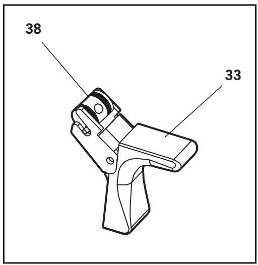
- Ensure Rotary Valve 38 is assembled in correct orientation, align pins with forks on the Trigger 33. See illustration below.
Trigger
Dismantling
Using a 4mm pin punch (07900-00158) drive Trigger Pin 46 out and remove Trigger 33.
- Unscrew Trigger Valve 21 using trigger valve extractor (0900-00692).
Assemble in reverse order to Dismantling Instructions noting the following:
- When assembling Trigger 33 the trigger forks locate on the pins each side of the Rotary Valve 38.
- Ensure Rotary Valve 38 is orientated correctly. See illustration below.
Item numbers in bold refer to the general assembly drawing and parts list on pages 26 and 27.
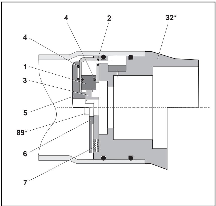
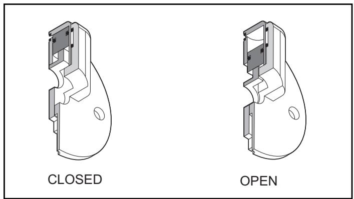
Assembly (see illustration below)
- Place 'O' Ring 2 into the recess in Housing 5 retain in position using grease Molykote® 55.
- Assemble 'O' Ring 4 onto Piston 1 and push assembly into Housing 5 making sure it is in as far as it will go.
- Position the slot in Piston 1 parallel to the step face in Housing 5.
- Slide Plate Shut Off 3 into the assembled parts 1, 2, 4, and 5. Retain parts in place using grease Molykote® 55.
- Place 'O' Ring 4 into the recess of Cover Plate 6 retain in position using grease Molykote® 55.
- Place spring 7 into position locate using the recesses in both Plate Shut Off 3 and Bottle Adaptor Assembly 32^* .
- Position the above assembled parts onto Bottle Adaptor Assembly 32^* .
- Secure in position using two Screws 89^* .
*see pages 26 and 27.
| ITEM | DESCRIPTION |
| 1 | PISTON |
| 2 | ‘O’ RING |
| 3 | PLATE SHUT OFF |
| 4 | ‘O’ RING |
| 5 | HOUSING |
| 6 | COVER PLATE |
| 7 | SPRING |
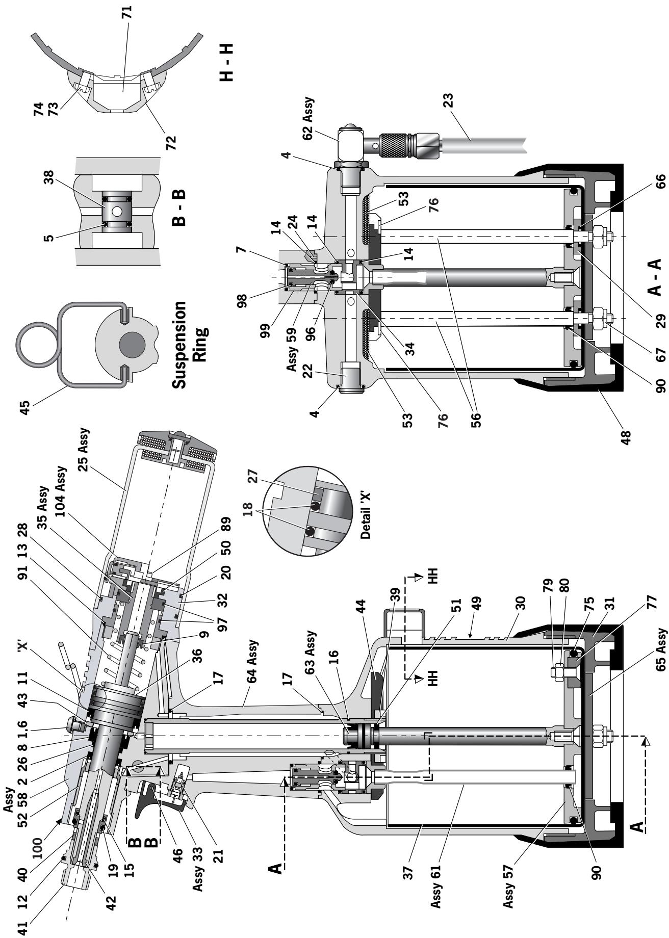
| 71223-02000 PARTS LIST | |||||||||
| ITEM | PART N° | DESCRIPTION | QTY | SPARES | ITEM | PART N° | DESCRIPTION | QTY | SPARES |
| 01 | 07001-00405 | M5x5 HEX SOCKET BUTTON HD BLEED SCREW | 1 | 43 | 71210-02019 | SEAL RETainer | 1 | ||
| 02 | 07003-00333 | LIP SEAL | 1 | 44 | 71213-02010 | TOP PLATE ASSEMBLY | 1 | ||
| 04 | 07003-00127 | 'O' RING | 2 | 45 | 71210-02022 | SUSPENSION RING | 1 | ||
| 05 | 07003-00189 | 'O' RING | 2 | 46 | 71210-02024 | TRIGGER PIN | 1 | ||
| 06 | 07003-00194 | M5 BONDED SEAL | 1 | 48 | 71221-02007 | RUBBER BOOT | 1 | ||
| 07 | 07003-00271 | 'O' RING | 1 | 49 | 71223-02027 | LABEL | 1 | ||
| 08 | 07003-00273 | LIP SEAL | 1 | 50 | 71213-02028 | RETAINING NUT | 1 | ||
| 09 | 07003-00274 | LIP SEAL | 1 | 51 | 71210-03205 | GUIDE RING | 1 | ||
| 11 | 07003-00341 | LIP SEAL | 1 | 52 | 71210-02104 | SEAL HOUSING | 1 | ||
| 12 | 07003-00277 | 'O' RING | 1 | 53 | 71210-02031 | SILENCER | 2 | ||
| 13 | 07003-00278 | 'O' RING | 1 | 56 | 71221-02004 | TIE ROD | 2 | ||
| 14 | 07003-00281 | 'O' RING | 3 | 57 | 71221-03210 | PNEUMATIC PISTON ASSEMBLY | 1 | ||
| 15 | 07003-00204 | 'O' RING | 1 | 58 | 71213-03320 | HEAD ASSEMBLY | 1 | ||
| 16 | 07003-00287 | 'O' RING | 1 | 59 | 71210-03400 | VALVE SPOOL ASSEMBLY | 1 | ||
| 17 | 07003-00288 | 'O' RING | 2 | 61 | 71230-03600 | TRANSFER TUBE ASSEMBLY | 1 | ||
| 18 | 07003-00342 | 'O' RING | 2 | 62 | 71210-03700 | ON/OFF VALVE ASSEMBLY | 1 | ||
| 19 | 07003-00310 | 'O' RING | 1 | 63 | 71210-03800 | INTENSIFIER SEAL ASSEMBLY | 1 | ||
| 20 | 07003-00415 | 'O' RING | 1 | 64 | 71213-02013 | HANDLE ASSEMBLY | 1 | ||
| 21 | 07005-00088 | TRIGGER VALVE | 1 | 65 | 71221-02014 | BASE PLATE ASSEMBLY | 1 | ||
| 22 | 07005-01274 | 1/8" BSP PLUG | 1 | 66 | 07003-00027 | 'O' RING | 2 | ||
| 23 | 07008-00010 | 6" FLEXIBLE HOSE | 1 | 67 | 07002-00108 | M6 NYLOC NUT | 2 | ||
| 24 | 07007-00224 | 3mm DIAx10mm SPIROL PIN | 2 | 71 | 71221-20105 | MODIFIED COUNTER | 1 | ||
| 25 | 71213-03800 | STEM COLLECTOR BOTLE ASSEMBLY | 1 | 72 | 71221-20101 | COUNTER MOULDING | 1 | ||
| 26 | 71213-02021 | BEARING TAPE - PISTON ROD | 1 | 73 | 71221-20103 | MOULDING RETAINING NUT | 2 | ||
| 27 | 71213-02022 | BEARING TAPE - PISTON | 1 | 74 | 71221-20102 | SPECIAL M4 SCREW | 2 | ||
| 28 | 07003-00416 | 'O' RING | 1 | 75 | 07003-00280 | 'O' RING | 1 | ||
| 29 | 71221-02006 | SEALING WASHER | 2 | 76 | 07002-00163 | WASHER | 2 | ||
| 30 | 71223-02001 | BODY MACHINED | 1 | 77 | 07007-01993 | CENTRE POLE MAGNET | 1 | ||
| 31 | 71221-02002 | BASE COVER | 1 | 79 | 71221-20104 | M5 X 19 COUNTERUNK SCREW | 1 | ||
| 32 | 71213-03000 | BOTTLE ADAPTOR ASSEMBLY | 1 | 80 | 07002-00098 | M5 NYLOK NUT | 1 | ||
| 33 | 71213-02008 | TRIGGER ASSEMBLY | 1 | 89 | 07001-00677 | SCREW | 2 | ||
| 34 | 71210-02009 | VALVE SEAT | 1 | 90 | 07003-00274 | LIP SEAL | 3 | ||
| 35 | 71213-02025 | END CAP ASSEMBLY | 1 | 91 | 07490-03002 | SPRING | 1 | ||
| 36 | 71223-02121 | HEAD PISTON | 1 | 96 | 07003-00268 | 'O' RING | 1 | ||
| 37 | 71221-02008 | CYLINDER LINER | 1 | 97 | 07003-00398 | 'O' RING | 2 | ||
| 38 | 71213-02012 | ROTARY VALVE | 1 | 98 | 07003-00042 | 'O' RING | 1 | ||
| 39 | 71210-02014 | CLAMP NUT | 1 | 99 | 71210-03401 | VALVE BODY | 1 | ||
| 40 | 71210-02103 | LOCKNUT | 1 | 100 | 07007-01503 | LABEL BOOK SYMBOL | 1 | ||
| 41 | 71210-02101 | JAW SPREADER HOUSING | 1 | 103 | 07900-00842 | TOOL INSTRUCTION MANUAL | 1 | ||
| 42 | 71220-02102 | VACUUM SLEEVE | 1 | 104 | 71213-03900 | STOP PLATE ASSEMBLY | 1 | ||
Priming is ALWAYS necessary after the tool has been dismantled and prior to operating. It may also be necessary to restore the full stroke after considerable use, when the stroke may be reduced and fasteners are not fully placed by one operation of the trigger.
Oil Details
The recommended oil for priming is Hyspin® VG32 available in 0.5 litre (part number 07992-00002) or one gallon containers (part number 07992-00006). Please see safety data below.
Hyspin® VG 32 Oil Safety Data
First Aid
SKIN:
Wash thoroughly with soap and water as soon as possible. Casual contact requires no immediate attention. Short term contact requires no immediate attention.
INGESTION:
Seek medical attention immediately. DO NOT induce vomiting.
EYES:
Irrigate immediately with water for several minutes. Although NOT a primary irritant, minor irritation may occur following contact.
Fire
Flash point 232^ . Not classified as flammable.
Suitable extinguishing media: CO_2 , dry powder, foam or water fog. DO NOT use water jets.
Environment
WASTE DISPOSAL: Through authorised contractor to a licensed site. May be incinerated. Used product may be sent for reclamation.
SPILLAGE: Prevent entry into drains, sewers and water courses. Soak up with absorbent material.
Handling
Wear eye protection, impervious gloves (e.g. of PVC) and a plastic apron. Use in well ventilated area.
Storage
No special precautions.
Priming Kit
To enable you to follow the priming procedure opposite, you will need to obtain a priming kit:
| PRIMING KIT : 07900-00688 | |
| PART № | DESCRIPTION |
| 07900-00351 | 3mm ALLEN KEY |
| 07900-00700 | PRIMING PUMP |
| 07900-00224 | 4mm ALLEN KEY |
| 07900-00698 | STOP NUT |
| 07900-00734 | STOP NUT - MAXLOK® |
IMPORTANT
DISCONNECT THE TOOL FROM THE AIR SUPPLY OR SWITCH OFF AT VALVE 55.
REMOVE NOSE ASSEMBLY OR SWIVEL HEAD COMPONENTS.
All operations should be carried out on a clean bench, with clean hands in a clean area.
Ensure that the new oil is perfectly clean and free from air bubbles.
Care MUST be taken at all times, to ensure that no foreign matter enters the tool, or serious damage may result.
- Switch OFF air supply at ON/OFF Valve Assembly 62.
- Remove all nose equipment. (see page 8)
- Remove Bleed Screw 1 and Bonded Seal 6.
- Invert tool over suitable container, switch ON air supply at ON/OFF Valve Assembly 62 and actuate tool.
- Residual oil in the tools hydraulic system will empty through bleed screw orifice.
CARE SHALL BE TAKEN TO ENSURE THAT THE BLEED HOLE IS NOT DIRECTED TOWARDS THE OPERATOR OR OTHER PERSONNEL.
- Switch air supply OFF at ON/OFF Valve Assembly 62.
- Screw priming pump (07900-00700) into bleed screw port, utilising Bonded Seal 6.
- Actuate Priming Pump by pressing down and releasing several times until resistance is evident and the Head Piston starts to move rearward.
ENSURE PUMP IS KEPT 'SQUARE' TO BLEED SCREW PORT DURING PRIMING OPERATION TO PREVENT BREAKAGE OF BLEED NIPPLE ON PRIMING PUMP.
- Remove the Priming Pump, surplus oil will expel from bleed screw port.
- Replace the Bleed Screw 1 together with Bonded Seal 6.
- Switch ON air supply at ON/OFF Valve Assembly 62.
- Check that the stroke of the Head Piston reaches specification. If not repeat above procedure.
- Switch OFF air supply and refit nose equipment. (see page 8).
| Symptom | Possible Cause | Remedy | Page Ref |
| More than one operation of the trigger needed to place fastener | Air leak | Tighten joints or replace components | |
| Insufficient air pressure | Adjust air pressure to within specification | 5 | |
| Worn or broken jaws | Fit new jaws | 8 | |
| Low oil level or air in oil | Prime tool | 28 and 29 | |
| Build up of dirt inside the nose assembly | Service nose assembly | 8† | |
| Tool will not grip stem of fastener | Worn or broken jaws | Fit new jaws | 8 to 12 |
| Build up of dirt inside the nose assembly | Service nose assembly | 8 | |
| Loose jaw housing | Tighten against locking ring | 8 | |
| Weak or broken spring in nose assembly | Fit new spring | 8 to 12 | |
| Incorrect component in nose assembly | Identify and replace | 9 to 12 | |
| Jaws will not release broken stem of fastener | Build up of dirt inside the nose assembly | Service nose assembly | 8† |
| Jaw housing, nose tip or nose casing not properly seated | Tighten nose assembly | 9 to 12 | |
| Weak or broken spring in nose assembly | Fit new spring | 9 to 12 | |
| Air or oil leak | Tighten joints or replace components | ||
| Low oil level or air present in oil | Prime tool | 28 and 29 | |
| Cannot feed next fastener | Broken stems jammed inside tool | Empty stem collector | 7 |
| Check jaw spreader is correct | 9 to 12 | ||
| Adjust air pressure to within specification | 5 | ||
| Slow cycle | Low air pressure | Adjust air pressure to within specification | 5 |
| Build up of dirt inside the nose assembly | Service nose assembly | 8† | |
| Tool fails to operate | No air pressure | Connect and adjust to within specification | 5 |
| Damaged Trigger Valve 21 | Replace | 23 | |
| Fastener fails to break | Insufficient air pressure | Adjust air pressure to within specification | 5 |
| Fastener outside tool capability | Use more powerful Genesis tool Contact Avdel | ||
| Low oil level or air present in oil | Prime tool | 28 and 29 |
† Page 17 if a swivel head is used instead of a nose assembly.
Item numbers in bold refer to the general assembly drawing and parts list on pages 26 and 27.
Other symptoms or failures should be reported to your local Avdel authorised distributor or repair centre.
Declaration of Conformity
We, Avdel UK Limited, Watchmead Industrial Estate, Welwyn Garden City, Herts, AL7 1LY declare under our sole responsibility that the product:
Model nG3
Serial No.
to which this declaration relates is in conformity with the following standards:
EN ISO 12100 - parts 1 & 2
BS EN ISO 8662 - part 6 BS EN ISO 11202
BS EN ISO 3744 BS EN 982
ISO EN 792 part 13-2000 BS EN 983
following the provisions of the Machine Directive 98/37/EC

A. Seewraj - Product Engineering Manager - Automation Tools
Date of issue

This box contains a power tool which is in conformity with Machines Directive 98/37/EC. The 'Declaration of Conformity' is contained within.
| NOM DE LA FIXATION | DIMENSION DE LA FIXATION (MM Pouples) | |||||||||||||
| 3 | 3.2 | 4.0 | 4.3 | 4.8 | 5 | 5.2 | 6 | 6.4 | 6.5 | 7 | 8 | 9 | 10 | |
| - | 1/8 | 5/32 | - | 3/16 | - | - | - | 1/4 | - | - | - | 3/8 | - | |
| AVEX® | ● | ● | ● | ● | ● | |||||||||
| STAVEX® | ● | ● | ● | |||||||||||
| AVINOX® II | ● | ● | ● | |||||||||||
| AVIBULB® | ● | ● | ● | ● | ||||||||||
| ETR | ● | |||||||||||||
| BULBEX® | ● | ● | ||||||||||||
| T-LOK® | ● | ● | ||||||||||||
| AVDEL® SR | ● | ● | ● | ● | ||||||||||
| MONOBOLT® | ● | ● | ||||||||||||
| INTERLOCK® | ● | ● | ||||||||||||
| AVTainer® | ● | ● | ||||||||||||
| AVDEL® | ● | ● | ● | |||||||||||
| MBC® | ● | ● | ● | |||||||||||
| MBC/LC® | ● | ● | ● | |||||||||||
| AVSEAL® II | ● | ● | ● | ● | ● | |||||||||
| Q™ RIVET | ● | ● | ● | ● | ||||||||||
| T™ RIVET | ● | ● | ||||||||||||
| CHERRYMATE™ | ● | ● | ||||||||||||
| KLAMPTITE™ | ● | ● | ||||||||||||
| KLAMPTITE™ KTR | ● | ● | ||||||||||||
EQUIPEMENT Ref. 71220-15400
REPERE
DESCRIPTION
REFERENCE
1
CARTER DE NEZ
07498-00501
2
JOINT TORIOLIE
07003-00067
9
BOITIER DE MORS
07498-00502
4
MACHOIRES
07497-03002
REPERE
DESCRIPTION
REFERENCE
10 G
DE RESSORT AVANT
07498-00507
7
RESSORT
07500-02005
11 GUL
DE RESSORT ARRIERE
07498-00503
8
BAGUE DE SERRAGE
07340-00327

REFERENCE DE L'OUTIL COMPLET :
EQUIPEMENT Ref. 71220-15500
REPERE
DESCRIPTION
REFERENCE
REPERE
DESCRIPTION
REFERENCE
1
CARTER DE NEZ
07498-00501
7
RESSORT
07500-02005
2
JOINT TORIOUE
07003-00067
11 G
DE RESSORT ARRIERE
07498-00503
a
BOITIER DE MORS
07498-00801
8
BAGUE DE SERRAGE
07340-00327
1
MACHOIPES
0722002302
12 ADAE
- D'FIECTION LATERAL
0740800000
4 10
DECOODT ALVANT
POUR LA POSE DES FIXATIONS
AVTainer® AVEC CET
EQUIPMENTPARTICULAR.

NEZ TYPE 6
REFERENCE DE
L'OUTIL COMPLET:
faire preceder de
71223-00
EQUIPEMENT
Réf. 71230-15800
| FASTENER | NEZ (mm) | voir ci-dessous | ||||
| Nom | Ø1 | MATERIALIAU | REFERENCE | 'A' | 'B' | |
| MONOBOLT® | 1/4 | 6.4 | Tous | 71220-16021 | 14.3 | 4.1 |
| INTERLOCK® | 1/4 | 6.4 | Tous | 07612-02001 | 14.3 | 3.6 |
| STAVEX® | 1/4 | 6.4 | Tous | 07612-02001 | 14.3 | 3.6 |
| REPÈRE | DESCRIPTION | RéÉRÊNCE |
| 1 | CARTER DE NEZ | 07340-00306 |
| 2 | JOINT TORIQUE | 07003-00067 |
| 3 | CARTER PORTE-MÂCHOIRES | 07612-02003 |
| 4 | MÂCHOIRES | 07612-02002 |
| 5 | PORTE-MÂCHOIRES | 07498-04502 |
| 6 | BUTOIR | 07498-03003 |
| 7 | RESSORT | 07500-00418 |
| 8 | BAGUE DE SERRAGE | 07340-00327 |
BESCHRÄNKTE GARANTIE
HINTERE FEDERFUIHRING
07498-00503
8
KLEMMRING
07340-00327
12
AUSWERFERADAPTER
07498-00900
13
VAKUUM-ABSPERRMUTTER
71233-20200
MUNDSTUCK (mm)
ART
'A'
unto
074
19
4
.243
KOMPLETES GERAT
NUMMER:
mit 71223-00
vorangehend.
NUR DAS MUNDSTUCK TYP 5 WURDE
SPEZIELL FUR DAS SETZEN DER
AVTainer-NIETEMITDIESER
SPEZIAL-AUSRUSTUNG KONSTRUIERT.
TYP 6
MUNDST CKE
KOMPLETTES GERÄT
TEILNUMMER:
mit 71223-00
vorangehend
AUSRUSTUNG
Art-nr. 71230-15800
FASTENER
| TIPO RIVETTO | DIMENSIONI (MM Pollici) | ||||||||||||||
| 3 | 3.2 | 4.0 | 4.3 | 4.8 | 5 | 5.2 | 6 | 6.4 | 6.5 | 7 | 8 | 9 | 9.5 | 10 | |
| - | 1/8 | 5/32 | - | 3/16 | - | - | - | 1/4 | - | - | - | - | 3/8 | - | |
| AVEX® | ● | ● | ● | ● | ● | ||||||||||
| STAVEX® | ● | ● | ● | ||||||||||||
| AVINOX® II | ● | ● | ● | ||||||||||||
| AVIBULB® | ● | ● | ● | ● | |||||||||||
| ETR | ● | ||||||||||||||
| BULBEX® | ● | ● | |||||||||||||
| T-LOK® | ● | ● | |||||||||||||
| AVDEL® SR | ● | ● | ● | ● | |||||||||||
| MONOBOLT® | ● | ● | |||||||||||||
| INTERLOCK® | ● | ● | |||||||||||||
| AVTainer® | ● | ● | |||||||||||||
| AVDEL® | ● | ● | ● | ||||||||||||
| MBC® | ● | ● | ● | ||||||||||||
| MBC/LC® | ● | ● | ● | ||||||||||||
| AVSEAL® II | ● | ● | ● | ● | ● | ||||||||||
| Q™ RIVET | ● | ● | ● | ● | |||||||||||
| T™ RIVET | ● | ● | |||||||||||||
| CHERRYMATE™ | ● | ● | |||||||||||||
| KLAMPTITE™ | ● | ● | |||||||||||||
| KLAMPTITE™ KTR | ● | ● | |||||||||||||
Codici parte
Rowville, Victoria 3178
Tel: +61 3 9765 6400
Fax:+61397656445
Email: info@acument.com.au
CANADA
Avdel Canada, a Division of Acument
Canada Limited
87 disco Road
Rexdale
Ontario M9W 1M3
Tel: +1 416 679 0622
Fax: +1 416 679 0678
Email: infoAvdel-Canada@acument.com
CHINA
Acument China Ltd.
RM 1708, 17/F., Nanyang Plaza,
57 Hung To Rd., Kwun Tong
Hong Kong
Tel: +852 2950 0631
Fax: +852 2950 0022
Email: infochina@acument.com
FRANCE
Avdel France S.A.S.
3-1 Chigasaki-Chuo, Tsuzuki-ku,
Yokohama-city, Kanagawa Prefecture
Japan 224-0032
Tel: +81 45 947 1200
Fax:+81459471205
Email: info@acument.co.jp
SINGAPORE
Acument Asia Pacific (Pte) Ltd.
05-03/06 Techlink
31 Kaki Bukit Road 3
Singapore, 417818
Tel: +65 6840 7431
Fax: +65 6840 7409
Email: Tlim@acument.com
| Manual No. | Issue | Change Note No. |
| 07900-00842 | B | 07/044 |
| B2 | 07/103 | |
| B3 | 07/174 | |
| B4 | 08/008 | |
| B5 | 08/171 |
SOUTH KOREA
Acument Korea Ltd.
212-4, Suyang-Ri
Silchon-Eup, Kwangju-City,
Kyunggi-Do, Korea, 464-874
Tel: +82 31 798 6340
Fax:+82317986342
Email: info@acumentkorea.com
SPAIN
Avdel Spain S.A.
C/Puerto de la Morcuera,14
Poligono Industrial Prado Overa
Ctra. de Toledo, km 7,8
28919 Leganés (Madrid)
Tel: +34 (0) 91 3416767
Fax: +34 (0) 91 3416740
Email:ventas@acument.com
UNITED KINGDOM
Avdel UK Limited
Pacific House
2 Swiftfields
Watchmead Industrial Estate
Welwyn Garden City
Hertfordshire
AL71LY
Tel: +44 (0) 1707 292000
Fax: +44 (0) 1707 292199
Email: enquiries@acument.com
USA
Avdel USA LLC
614 NC Highway 200 South
Stanfield,
North Carolina 28163
Email: infoAvdel-USA@acument.com